jintay-locks oem-flow-1

What a DFM Design Review Actually Checks

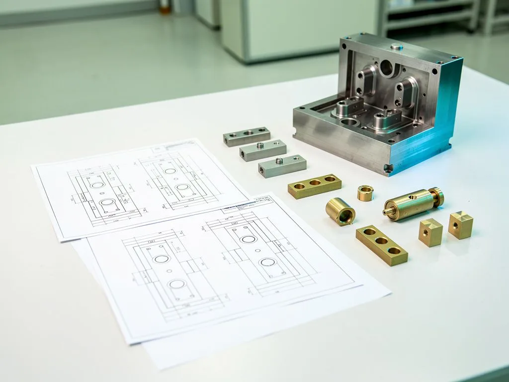
DFM (Design for Manufacturing) is the first gate before an OEM lock moves from drawings to mass production. It simultaneously checks whether the part structure can be stably formed in the mold, whether the assembly sequence is logical, whether the cost structure falls within the target range, and whether the subsequent certification path is viable. For buyers, the value at this stage is to catch problems that are "visible on the drawing but impossible on the production line" at the lowest cost, avoiding the discovery only after samples are made that the mold needs to be re-cut.
Key Takeaways

  • DFM is the first gate before mass production

    Before OEM locks move from drawings to mass production, DFM checks whether part structures can be molded consistently, whether assembly sequences are reasonable, whether cost structures fall within target ranges, and whether certification paths are feasible.

  • DFM examines three major structural aspects

    When evaluating lock structures, DFM checks part geometry and draft angles, wall thickness and shrinkage rates, and assembly sequence and tolerance chains, to avoid discovering that new molds are needed only after samples are completed.

  • Four types of information are needed before submitting for DFM

    Buyers need to prepare 3D files and 2D engineering drawings, target market and usage descriptions, estimated order quantities and unit price ranges, and known usage scenario constraints, to keep the evaluation focused.

  • DFM reports should be judged from three dimensions

    Buyers should evaluate technical risk, cost, and schedule to decide whether to proceed to mold development, and arrange a formal review meeting to confirm modification suggestions item by item.

What aspects of lock structure does a DFM review examine?

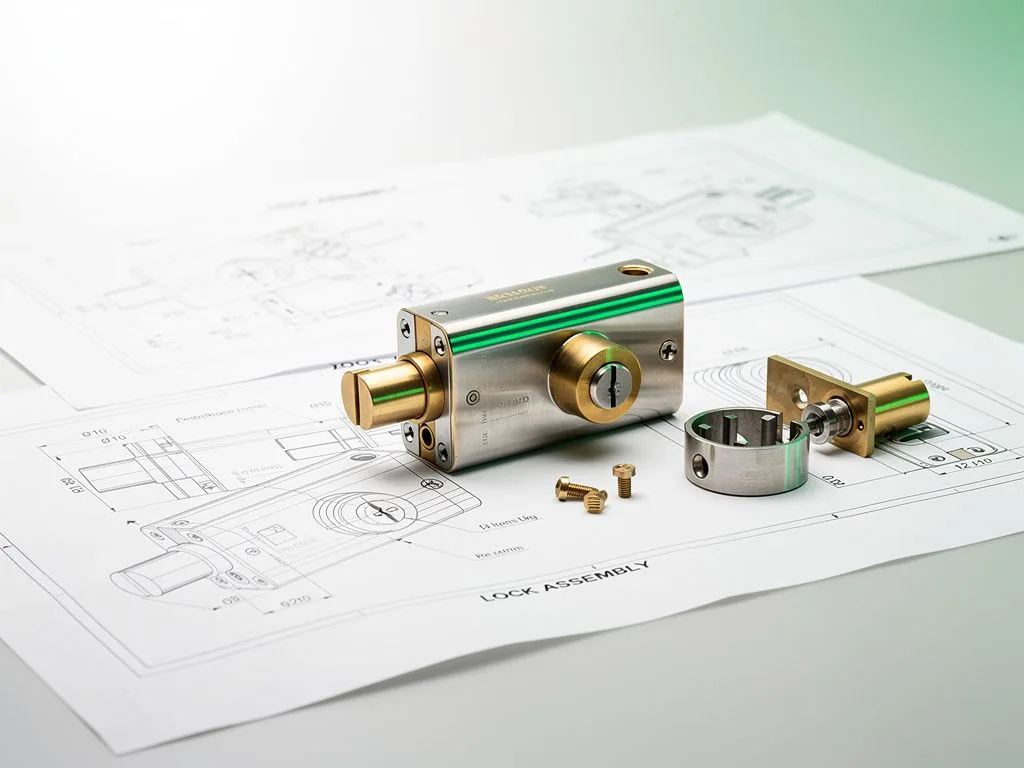
When reviewing lock structure, the first check point in a DFM assessment is part geometry and draft angle. Inside the lock body are the cylinder, pins, gears, or electronic modules, so the housing must be able to open the mold smoothly and avoid undercuts; otherwise, sliders or secondary injection molding are required, which significantly increases cost. For example, if the cylinder hole of a TSA luggage lock is designed on the parting line, it directly affects the concentricity of subsequent key alignment. At the DFM stage, it would be recommended to shift the hole position by a few tenths of a millimeter to keep the parting line away from the functional surface. The second check point is wall thickness and shrinkage rate. If the wall thickness of a zinc alloy die-cast part is uneven, shrinkage porosity can easily occur after solidification. Products like TSA locks, which need to pass customs opening torque tests, are particularly sensitive to this. Thin-wall areas may also cause cold shuts or short shots. If the buyer does not mark the critical wall thickness areas on the drawing, the evaluation team can only guess based on experience. The third check point is assembly sequence and tolerance chain. If the cylinder hole position, shackle groove, and button travel interfere with each other, it directly affects feel and lifespan. This is especially true for the dial mechanism of combination locks; if the accumulated tolerances of each dial are not properly allocated, the rotational resistance of the entire lock will be inconsistent. If buyers can mark "which dimensions are critical and which are reference" before sending drawings, the review meeting will be more focused and can also prevent the factory from treating all dimensions as critical, which would unnecessarily increase mold costs.

What materials should buyers prepare before submitting a DFM request?

The materials buyers need to prepare before submitting a DFM request can be divided into four categories. The first is 3D files and 2D engineering drawings, primarily in STEP or IGES format, with material, surface finish, and critical dimension tolerances marked on the drawings. If only 3D files are provided without 2D engineering drawings, it is difficult for the factory to determine which dimensions are truly important to the designer and which are only for reference. The second is target market and application description, such as "TSA luggage lock for the US market" or "locker lock for European gyms." This directly determines certification requirements and material selection. Even for the same type of padlock, a TSA lock must pass customs opening torque tests, while a European locker lock may need to meet EN standards for wear resistance in public spaces. The differences in material and surface treatment between the two are considerable. The third is estimated order volume and target unit price range. The DFM team will use this to determine whether to use a single-cavity or multi-cavity mold, and whether a progressive die is worthwhile. The mold amortization model is completely different depending on the annual order volume range. If the buyer does not provide an estimated volume, the factory can only assume a conservative number, which may overestimate the unit cost. The fourth is any known usage constraints, such as outdoor exposure, low-temperature environments, or required IP-rated dust and water resistance. If these conditions are not clearly stated during the evaluation stage, they are often only discovered during the certification stage, when modification costs are highest and time-to-market is affected.

Six items typically checked in a DFM review meeting

  • Mold feasibility

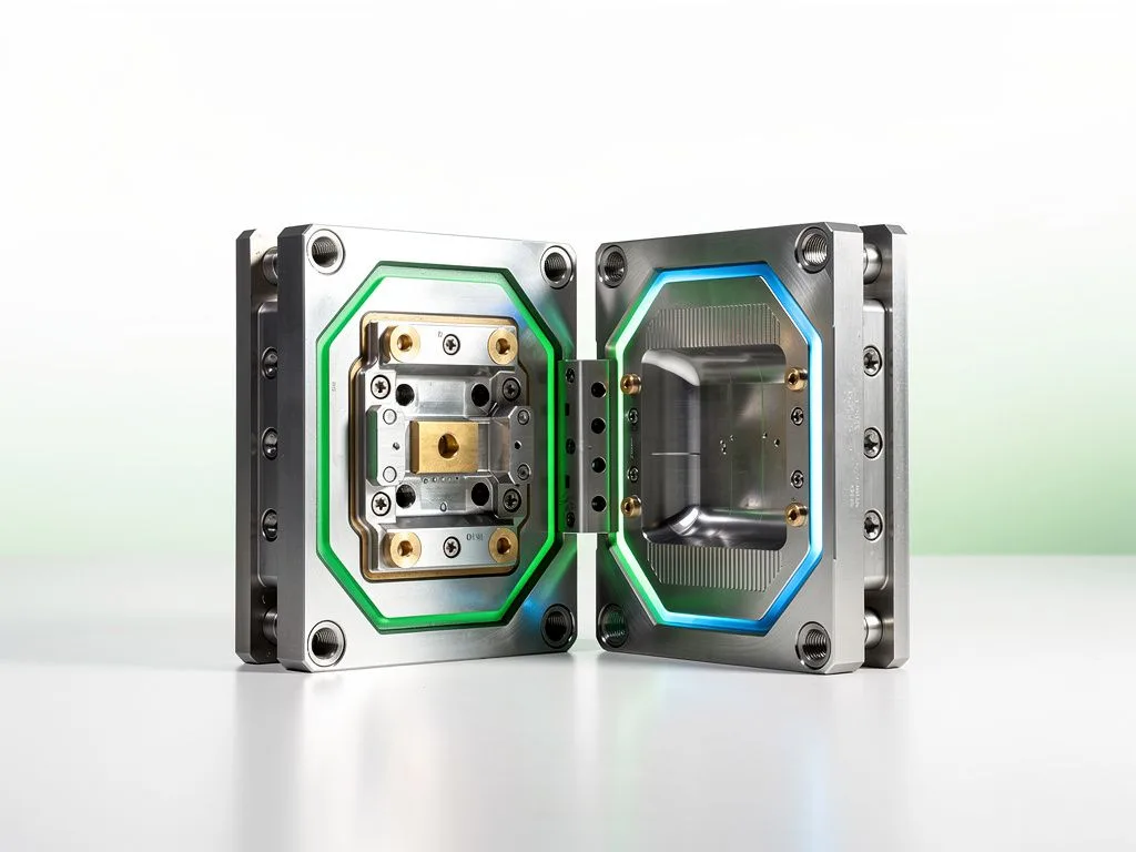
    Checks parting line position, draft angle, undercut handling, and slider count to assess single-mold cost and lifespan.

  • Material and process compatibility

    Confirms the correspondence and yield rates of materials such as zinc alloy, ABS, and stainless steel with injection molding, die casting, and CNC.

  • Assembly sequence and labor hours

    Breaks down the assembly path of the cylinder, springs, and housing to estimate per-unit assembly time and automation potential.

  • Cost structure breakdown

    Itemizes unit costs and optimization opportunities for materials, mold amortization, surface treatment, assembly, and packaging.

  • Certification and compliance path

    Lists required tests for the target market and indicates which can be done in-house and which must be outsourced.

  • Risks and alternatives

    Flags high-risk design points and proposes alternative structures to avoid forced mold re-cutting later.

oem flow scene 1

Will IoT module integration be discussed during the DFM stage?

Yes, and this is one of the most underestimated aspects of smart lock OEM projects. Bluetooth, NFC, and RFID modules each have different antenna placement requirements, and the fit between the PCB size and the lock body cavity directly affects wireless performance. The DFM review will check the battery compartment space, waterproof gasket grooves, the detachable structure for charging or battery replacement, and the antenna clearance area for the cloud connectivity module. For buyers, the most common blind spot at this stage is designing the mechanical structure first and then trying to force the electronic module in afterward. The result is that once the module is installed, the antenna is shielded by the metal housing, and the signal range drops from the expected 10 meters to 2 meters, effectively stripping the lock of its IoT value. Another common issue is that the battery compartment design fails to account for how users will actually replace the batteries, leading to post-production complaints that the entire lock must be disassembled just to change the battery. We recommend that buyers provide the electronic functional specifications, expected battery life, and target usage scenarios at the time of DFM submission so that the mechanical and electronic aspects can be evaluated in parallel. If the electronic specifications are still subject to change, this should be marked as "to be confirmed" in the DFM report to prevent the factory from assuming the specifications are final and proceeding with tooling that may later need to be revised.
After the DFM report is issued, how should buyers decide whether to move forward?

After the DFM report is issued, buyers should evaluate whether to proceed based on three dimensions. The first is technical risk: can the red-flag items (high-risk design points) identified in the report be resolved without sacrificing functionality? If significant changes to the original design are required, the project timeline must be reassessed. Common red flags include undercuts that cannot be released from the mold, critical wall thicknesses exceeding process limits, or assembly sequences that conflict with the PCB layout. The second dimension is cost: does the unit cost fall within the target range, and does the mold amortization fit the payback model based on the projected order volume? Buyers who only look at the unit cost without considering the mold amortization share often discover after mass production that the actual cost is higher than expected. The third dimension is schedule: does the timeline from DFM closure to prototyping and then to mass production align with the buyer's launch date? This is especially critical for locks with seasonal demand, such as luggage locks before the travel season—if the schedule is missed, the next opportunity is the following season. After receiving the report, we recommend that buyers arrange a formal review meeting to go through the modification suggestions and alternative solutions item by item before deciding whether to proceed to the mold development stage. This decision point often has a greater impact on project success than any subsequent stage.

Process from DFM completion to prototyping

  1. 1

    Mold design and CNC programming

    The factory draws the mold based on the DFM conclusions, and buyers can re-confirm the parting line position and surface texture to avoid the appearance of trial molding differing from expectations.

  2. 2

    Mold making and trial molding

    Zinc alloy die-casting mold production takes longer, so buyers can prepare surface treatment, color chips, and packaging design in parallel, so that once samples are produced, they can immediately enter the full sample stage.

  3. 3

    First article inspection and dimensional report

    The factory provides first article dimensional measurement data and appearance inspection reports, and buyers confirm before entering mass production. Buyers can also request material certificates for trial molding materials and yield data.

oem flow scene 2

The three most common pitfalls in the DFM stage

The three most common pitfalls in the DFM stage are: version confusion in drawing files, unclear certification targets, and treating DFM as a mere drawing check. The first pitfall is version confusion. When different departments within the buyer's organization update dimensions separately, the version sent to the factory may not match the version actually intended for production, invalidating the evaluation results. We recommend that buyers assign a single point of contact for version control before sending drawings and include the drawing version and date in the email subject line. The second pitfall is unclear certification targets. Many buyers simply say they are targeting the European or American market without specifying whether they need TSA locks, the CE Machinery Directive, or specific fire safety regulations for public spaces. The DFM team is left to guess, and if the guess is wrong, the process has to start over. Even within the European market, the EN standards applicable to locker locks and door locks are completely different, and the material and structural requirements differ accordingly. The third pitfall is treating DFM as a simple drawing check, overlooking that it is actually a comprehensive decision-making platform covering cost, labor hours, certification, and risk. If the buyer only checks whether the drawings are correct without assessing overall project feasibility, they may only discover after mass production that a particular design point pushes the unit cost over budget. We recommend that buyers assign a single point of contact for DFM coordination to avoid information being scattered across different emails and instant messages, and treat the DFM report as a project decision document rather than a technical attachment.

What happens between DFM closure and prototyping?

Between DFM closure and prototyping, there are typically three sub-stages. The first is mold design and CNC programming, where the factory creates the mold drawings based on the DFM conclusions. Buyers can use this stage to reconfirm the parting line position and surface texture. If this is not confirmed at this stage, the appearance of the parts produced during trial molding may differ from what was originally envisioned, and the cost of making changes later will be higher than doing so now. The second is mold fabrication and trial molding. Zinc alloy die-casting molds typically have a longer production cycle, and during this period buyers can prepare surface finishing, color cards, and packaging design in parallel, so that once the prototype is produced, it can move directly into the full sample stage rather than waiting for the parts to arrive before starting to look for a surface finishing supplier. The third is first article inspection and dimensional reporting. The factory will provide first article dimensional measurement data and an appearance inspection report, and mass production will only begin after the buyer confirms these. The transparency of progress across these three sub-stages is an important indicator of whether an OEM partner is mature. A mature factory will proactively provide weekly reports and issue lists rather than waiting for the buyer to chase them. Buyers can also request material certificates for the trial molding material and preliminary yield data at this stage, which can serve as a baseline for subsequent mass production.

How should buyers turn DFM findings into an actionable decision list?

The value of a DFM report lies not in whether problems exist, but in how the buyer acts on the report. The first step is to sort the red, yellow, and green items from the report into three separate lists. Red items must be resolved before tooling begins, yellow items can be verified during the trial run phase, and green items serve as references for subsequent optimization. The second step is to map each modification suggestion to the version differences in the original drawing files, so the factory knows exactly what to change, why, and what the expected outcome is—rather than simply being told to "modify per the DFM report" and left to interpret it on their own. The third step is to set a review cycle, recommending that the buyer and factory sync on the implementation progress of DFM conclusions every two weeks until all red items are closed. For buyers, DFM is not a one-time meeting but an ongoing decision loop that continues until the pre-sample stage. Managing this loop well will significantly reduce rework rates and communication costs during mass production.

FAQ

What aspects of lock structure does the DFM evaluation check?

When evaluating lock structures, the first check point is part geometry and draft angles, the second is wall thickness and shrinkage rates, and the third is assembly sequence and tolerance chains. Inside the lock body there are cylinders, pins, gears, or electronic modules, and the housing must be able to be molded smoothly without undercuts, otherwise costs will rise significantly.

What information should buyers prepare before submitting for DFM?

Buyers need to prepare four types of information: 3D files and 2D engineering drawings (with material, surface finish, and critical dimension tolerances annotated), target market and usage descriptions, estimated order quantities and unit price ranges, and known usage scenario constraints. If only 3D files are provided without 2D engineering drawings, it is difficult for the factory to determine which dimensions are critical.

Will IoT module integration be discussed during the DFM stage?

Yes, and this is the most commonly underestimated part of smart lock OEM. The DFM evaluation checks battery compartment space, waterproof gasket grooves, detachable structures for charging or battery replacement, and antenna clearance areas for cloud connectivity modules. It is recommended that buyers provide electronic function specifications, expected battery life, and target usage scenarios all at once when submitting for DFM.

After the DFM report is issued, how should buyers decide whether to proceed?

Buyers should evaluate from three dimensions: technical risk (whether red-flag items can be resolved without sacrificing functionality), cost (whether unit cost falls within the target range and mold amortization aligns with the payback model), and schedule (whether the timeline aligns with the launch date). It is recommended to arrange a formal review meeting to confirm item by item.

What are the three most common pitfalls during the DFM stage?

The three pitfalls are: version confusion in drawing files (it is recommended to assign a single point of contact for version control), unclear certification targets (TSA, CE, or specific EN standards need to be specified), and treating DFM as a simple drawing check (ignoring that it is a comprehensive decision platform covering cost, labor hours, certification, and risk).

Bring your lock design for a DFM evaluation

If you are evaluating OEM collaboration for TSA padlocks, combination locks, or IoT smart locks, feel free to provide your drawings and target market details. During the DFM stage, we will review the structure, certifications, and cost structure simultaneously and provide you with a decision-ready evaluation report.